Homemade Engraving Machine

Kenway

New Member
Joined
Feb 23, 2021
Messages
2
Hey!

I'm really interested in engraving but have no experience whatsoever. The GRS machine seems steep to me, especially if I'm not skilled or experienced. I want to build the homemade engraving machine, but all the links are dead.

I know some of you guys recommend going to a workshop to try out but the thing is I'm from Singapore, and we don't really have any hand engraving courses.

I hope you guys can help me!
 

tdelewis

Elite Cafe Member
Joined
Oct 10, 2010
Messages
752
Location
Volant, PA 60 miles north of Pittsburgh
There are several YouTube videos that show how to make a pneumatic machine from a small compressor. I have watched the video and they seem to work well. Do some searching on YouTube and I'm sure you will be interested.
 

dogcatcher

Elite Cafe Member
Joined
Oct 6, 2013
Messages
486
Location
Abilene TX Ruidoso NM
Look at this one.
If you have access to a metal lathe it is easy to make, by hand with drill and files, it is still easy, just an experience in old time "machining".
 

monk

Moderator
Staff member
::::Pledge Member::::
Joined
Feb 11, 2007
Messages
10,857
Location
washington, pa
Hey!

I'm really interested in engraving but have no experience whatsoever. The GRS machine seems steep to me, especially if I'm not skilled or experienced. I want to build the homemade engraving machine, but all the links are dead.

I know some of you guys recommend going to a workshop to try out but the thing is I'm from Singapore, and we don't really have any hand engraving courses.

I hope you guys can help me!
i made one shown by shaun hughes. they do work. and are very cheap to make compared to lindsay or grs. it's the old addage, "you get what you pay for". convenience/reliability, or inconvenience and maybe some problems.
 

Doctorslava

Member
Joined
Nov 5, 2018
Messages
72
Location
Atlanta, GA
I also made one. Been unable to compare with GRS or Linsay all I can tell, my skills are weakest link here. Machine works just fine. And hey, materials cost $150 only.
 

Ryan138

Elite Cafe Member
Joined
Jan 20, 2020
Messages
123
Location
Dayton, OH
Rick Alexander has an easy video to follow. I built mine inspired by the one he made. He also makes hand pieces for them. If you have a drill you can make a minimal version of this A3F3655C-F369-482E-BF89-194B87EAC872.jpeg
 

Attachments

  • 99B7C360-2B7C-4CD5-AFA2-9A55718DC0AC.jpeg
    99B7C360-2B7C-4CD5-AFA2-9A55718DC0AC.jpeg
    69.7 KB · Views: 64
  • 4ADF3285-44BD-4113-9C57-72F05758869A.jpeg
    4ADF3285-44BD-4113-9C57-72F05758869A.jpeg
    70.1 KB · Views: 60

hdvoyager

Member
Joined
Jun 2, 2020
Messages
14
Location
Scotch Grove, Iowa
I decided that since I haven't done any engraving yet, the cost of a Lindsay or GRS system can't be justified. Building a working graver system seemed like a good idea. besides, I love to invent and follow my own path.

To this end, I invented a new simplified graver which uses a Bar-Bell shaped piston that exhausts the pressurized air each stroke from behind the piston. The graver uses a constant air pressure, idle at 10#, working pressure 30# up to 60# or more. The frequency of the oscillations increase as the piston is pressed in and the power of the piston increases with the air pressure.

Criteria: use less air, start at Air On, and be easy to make (requiring a metal lathe). The piston rides in a machined tube, constant diameter. The Palm Rest seales the back of the graver. The Bit Holder doubles as the Anvil. The Piston must be located with air in with the necked down center directly at the Air In hole. To accomplish this, two springs are required, a weak spring under the rear of the piston and a slightly stronger spring at the front of the piston.

Piston design: The piston is constant diameter with a necked down center section. A .099" cross hole is drilled, intersecting a .099" hole drilled from the rear intersecting the cross hole. To retain the springs, a short extension, spring ID diameter, is added to each end of the piston. With the springs fully compressed, the extension keeps the spring from bottoming out.

The piston is made from 1045 carbon steel which can be hardened. 1045 is a common steel used by many custom blacksmith hammer makers, it is tough and doesn't chip or crack easily.

The Tube houses the piston and Bit Holder. Drilling out bar stock results in GALLING marks in the ID. The biggest challenge is eliminating galling all together. I achieved acceptable results as follows: Steel 12L14 has excellent machining properties. To make a drilled, several machining steps; center drill, drill a thru hole undersized and bore to size. The bored hole will be round, smooth, and consistent diameter.

Drill the Air Exhaust hole a specified distance from the Air In hole. The Piston length dimensions determine this distance. Hole edge dimensions are used for this calculation. Criteria: with the piston centered, the air in passes thru the cross hole/piston hole into the rear air chamber. As the piston moves forward, the Air out hole must be covered until the air in hole is covered by the rear piston section. As the piston continues forward, the rear air out holes are uncovered and the pressurized air at the rear of the piston is expelled very quickly. The front spring pushes the piston back to the rear to start the oscillation cycle over again.

The Piston fit to the Tube ID is critical! A fit with .001" gap will waste a lot of air. I turn the Tube ID first and then fit the piston to the hole. Turn the lathe's Compound to about a 10 degree angle. The compound can be turned .010" yet the SHARP lathe bit will advance about .0001" for very fine cuts. When the piston can forceable be inserted into the Tube, all fitting is done by sanding the spinning piston with 220 grit wet/dry sandpaper with WD-40 as a lubricant. The end result is a smooth sliding fit with no side play. This fit will greatly minimize air leakage!!!! yet allow free sliding travel of the piston.

These pictures will illustrate this graver design.


DSCN1614.JPG

The graver disassemble,. L-R :p
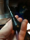
alm Rest, Piston with top/bottom springs, Bit Holder/Anvil Adjuster Cap
Bottom the Tube; L-R Threaded both ends, Bit holder alignment slot, front air relief hole, Air in fitting, Air out holes.


DSCN1620.JPG
The Tube showing it is constant diameter, no constrictions.

Is there any interest in a new Pneumatic Graver design?
 

hdvoyager

Member
Joined
Jun 2, 2020
Messages
14
Location
Scotch Grove, Iowa
Theory of operation. TtnwY4-NextDocument copy.jpg

The piston has reduced diameter center section. The Cross Hole is drilled in this center section which connects to the hole drilled latterly . With the piston positioned by the springs, the Air In Hole is opposite the piston's cross hole. The Air Out Hole is covered by the rear section of the piston.

The air is turned on and enters the Air In fitting, thru the piston cross hole into the space at the rear of the piston. The Palm Rest has the rear of the Tube sealed. The air pressure builds and shoots the piston forward.

When then piston reaches full forward, the pressure at the rear of the piston is released thru the Air Out Holes in the Tube. The air presure and front spring push the piston back to the rear.

Two things are happening; 1, the return spring starts the piston to the rear aided some air pressure built up in the front. 2. Piston momentum is the force to drive the piston past it's dead center position.

The above diagrams show the piston in the Start, Forward and Rear positions.

Critical spacing: The diameter of the Air In/Out holes are part of the spacing criteria and length of the bottom, center and front sections of the piston.. At no time can Air In and Air Out be connected in a crossover condition..

If I get enough interest, I will make a set of drawings of the operating pictured graver.
 

hdvoyager

Member
Joined
Jun 2, 2020
Messages
14
Location
Scotch Grove, Iowa
Some popular commercial systems and Youtube versions, have a Constrictor Ring located just behind Air In inlet hole. There are several machining problems as a result of this design. The Cylinder and the Constriction Ring must be perfectly concentric. The Piston has two diameters that must be a perfect simultaneous, concentric fit. Both sections must be tight about a .0001" looseness to prevent AIR LEAKAGE. The Piston must freely slide in the cylinder. This degree of tight tolerances are almost impossible to single point turn the critical parts.

Accordingly, a graver made ot a .001" tolerance overall will work and use an excessive amount of air.

Figure out the displacement volume of your piston. Radius squared X 3.14 X stroke length = volume displacement. Multiply by strokes per Minuit will give the Cubic Inches per Minuit used to drive the piston. Air leakage is waste air that needs to be supplied by the compressor. in addition to the air used to drive the piston.

As the Piston Diameter is decreased and the stroke length decreases, much less air will be used.

A light weight piston will travel faster than a heavy piston. The impact of the heavy piston will be more than the light weight piston, all conditions being equal..

The Bar-Bell system used a heavy, tight fitting piston. There are no concentric problems with my design. My system because the waste air losses are minimized runs on about .026 In cubed/stroke. @ 1000 stroks per min. =2.6 cubic inches per min. (3/8" piston diameter, 1/4" stroke. A piston .300" diameter, 1/4" stroke will use 1.7 cubic inches per min. @ 1000 strokes.)
 

hdvoyager

Member
Joined
Jun 2, 2020
Messages
14
Location
Scotch Grove, Iowa
i would be glad to help you build this graver design. What do you have for a lathe? Lathe experience level? You will need a small boring bar that can bore 2" depth at a .300 diameter. You can make one 0ut of a 1/4" lathe bit. I used 5-C collets as my chuck introduced chatter. 3-C collets will work also.
 

hdvoyager

Member
Joined
Jun 2, 2020
Messages
14
Location
Scotch Grove, Iowa
gtsport,

You are the only one to respond to my Thread. I am glad to help you make a functioning Graver. Somehow, we should correspond by Email. The question is, how to trade Email addresses.

This graver probably should be called An Air Hammer as it is powerful. I have several more ideas on how to retain the power and use less air by going to a smaller diameter piston and adjusting the stroke. The quick air dump at the rear of the piston is unique. The full power of the air pressure (PSI) applied to the base of the piston drives the piston forward. The piston acquires considerable "overshoot" at each end of the power stroke.

What do you have for a lathe? Tooling? I amusing a 11" Logan lathe vintage 1952 with 5-C collets. My 4 jaw chuck doesn't hold as well as the collets.
 

gtsport

Elite Cafe Member
Joined
Feb 16, 2007
Messages
305
Location
Racine, wisconsin
My home lathe is an Atlas 618 6 inch model, but I have a Sharp tool room lathe at work that I can use if need be. My skill level is tenacious amateur, I have a fair pile of failures to show for my successes. My E-mail address is gtsport at aol dot com. Looking forward to giving this a try!
 

willow52

New Member
Joined
Apr 18, 2022
Messages
2
Have just read this post several times and am really tempted to have a crack at making one of these gravers - rather than the Blow/Suck versions necessitating the modification (ruin?) of a perfectly good tyre inflating compressor.

Don't mean to criticise those who have made these modified compressor type gravers - they seem to have set the basic rules as to how this system can be easily made. I have seen your diagram showing the principles of operation of your Barbell piston system, but am wondering if you have ever made drawings of the parts needed to make one from scratch showing dimensions etc; of all the parts required to build the whole thing?

I do possess A Sieg Mini lathe which is accurate enough to get away with the machining parts, and am quite happy in my own ability to be able to do it successfully - just need the basics when it comes to all the correct dimensions. I would prefer to avoid all the 'trial and error' stages I would inevitably go through when trying to make something from the scant information available...

Hopefully you can help me out?

Regards and much respect, willow52
 

willow52

New Member
Joined
Apr 18, 2022
Messages
2
Hi hdvoyager,

Can I ask if you ever produced drawings for your handpiece? Would like to know the distance between the air inlet hole and the air outlet hole (centre to centre if possible). Have worked out most of the rest of what would be required to re-produce your design, but getting the correct relationship between in and out of the air would seem to be crucial if it is ever going to work correctly. Would also like the accurate dimensions of the piston as well - just to make sure everything lines up correctly.

Hope you can help me out on this, would be greatly appreciated...

Regards, willow52
 
Top