Martin Strolz
Elite Cafe Member
A detailed view
by Martin Strolz
Aside of the excellent advice available today, e.g. on Sam Alfanos DVD “The Expert`s guide to Graver Sharpening” which is more for the practical part of sharpening itself I thought it might be helpful to draw some details on gravers. I hope my drawings can bring some light in the way all these angles and planes are connected together. The article is more theoretical and will not help you making your tool cut better, but should enhance your imagination of it.
1.
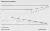
On page one I have tried to compare common European and American styles of grinding the same tool. I even used the same angles in the drawing, knowing that for air assisted engraving the tool at the bottom would not work well. The European style tool is for palm pushing only.
My goal is to focus your concentration on the most important three planes that form the tip and cutting edges of our tools.
The main difference is the length of the edge at the belly of the European tool and it’s rather high angle there. All theoretical considerations and conclusions in the following apply on both tools!
2. a
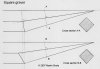
Page two shows the influence of the tool rotation angle (tool dial on the sharpening fixture) when grinding. In order to be compareable I have drawn the tools with complete and sharp tips, without a face. You may notice that the tools facets are of the same length.
With other length of the facets, you would have different looking side views but the same effects on the cross sections.
In figure A at the top you can see a tool ground at a somewhat strange angle for one reason. It can be seen very clearly that the top edges of the facets of the belly fall together with the symmetric line of the fore end. The ground part has the shape of a pyramid with a square base. Thus a cross section perpendicular to the symmetric line is a square. See also page 3 for this one.
In figure B the graver is ground quite extreme. To reach similar angles you must go to a rotation of maybe 55° or more. In this example a cross section cannot be square. I find it interesting how very slightly it changes the tools cross section compared to figure A.
The Italian bulino is somewhere in between example A and B.
2. b
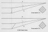
Page two second part. A graver like C you get when you set the tool dial at 45°. If you look closer, you notice that the symmetric line of the fore end meets the symmetric line of the tools shaft not at the left top corner of the facet, in fact a little to the left. Therefore the cross section is very slightly changed to a wider angle. This is my basic grinding angle for a tool for extreme shading.
But it will not handle nicely for engraving a bent line. It’s cuts are very narrow and drag will occur.
On example D you can see a fairly wide angled tool. Rotation could be in range of about 35°. If you look at the cross section, you notice that the side corners are lowered much thus forming a wide angle. I use such a tool for general purposes, maybe not fully that wide, but very similar.
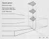
3.
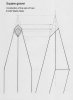
This page is to show, that a tool tip is like a pyramid. In this case the tool is ground like figure A of page 2. A face of a tool is always shaped like a deltoid, when the base of the pyramid is square.
4.
On this page you can see that only a few degrees more or less can change the angle of the face dramatically. This may have more effect on the tools angle between the cutting edges than the angle of rotation which determines the side facets. In fact those two play together!
No matter which one you alter, the angle between your cutting edges will change.
Face angles are dictated mostly by the hardness or toughness of the material you are cutting. Therefore you may like to determine the angle between cutting edges by the angle of rotation when grinding your tool.
by Martin Strolz
Aside of the excellent advice available today, e.g. on Sam Alfanos DVD “The Expert`s guide to Graver Sharpening” which is more for the practical part of sharpening itself I thought it might be helpful to draw some details on gravers. I hope my drawings can bring some light in the way all these angles and planes are connected together. The article is more theoretical and will not help you making your tool cut better, but should enhance your imagination of it.
1.
On page one I have tried to compare common European and American styles of grinding the same tool. I even used the same angles in the drawing, knowing that for air assisted engraving the tool at the bottom would not work well. The European style tool is for palm pushing only.
My goal is to focus your concentration on the most important three planes that form the tip and cutting edges of our tools.
The main difference is the length of the edge at the belly of the European tool and it’s rather high angle there. All theoretical considerations and conclusions in the following apply on both tools!
2. a
Page two shows the influence of the tool rotation angle (tool dial on the sharpening fixture) when grinding. In order to be compareable I have drawn the tools with complete and sharp tips, without a face. You may notice that the tools facets are of the same length.
With other length of the facets, you would have different looking side views but the same effects on the cross sections.
In figure A at the top you can see a tool ground at a somewhat strange angle for one reason. It can be seen very clearly that the top edges of the facets of the belly fall together with the symmetric line of the fore end. The ground part has the shape of a pyramid with a square base. Thus a cross section perpendicular to the symmetric line is a square. See also page 3 for this one.
In figure B the graver is ground quite extreme. To reach similar angles you must go to a rotation of maybe 55° or more. In this example a cross section cannot be square. I find it interesting how very slightly it changes the tools cross section compared to figure A.
The Italian bulino is somewhere in between example A and B.
2. b
Page two second part. A graver like C you get when you set the tool dial at 45°. If you look closer, you notice that the symmetric line of the fore end meets the symmetric line of the tools shaft not at the left top corner of the facet, in fact a little to the left. Therefore the cross section is very slightly changed to a wider angle. This is my basic grinding angle for a tool for extreme shading.
But it will not handle nicely for engraving a bent line. It’s cuts are very narrow and drag will occur.
On example D you can see a fairly wide angled tool. Rotation could be in range of about 35°. If you look at the cross section, you notice that the side corners are lowered much thus forming a wide angle. I use such a tool for general purposes, maybe not fully that wide, but very similar.
3.
This page is to show, that a tool tip is like a pyramid. In this case the tool is ground like figure A of page 2. A face of a tool is always shaped like a deltoid, when the base of the pyramid is square.
4.
On this page you can see that only a few degrees more or less can change the angle of the face dramatically. This may have more effect on the tools angle between the cutting edges than the angle of rotation which determines the side facets. In fact those two play together!
No matter which one you alter, the angle between your cutting edges will change.
Face angles are dictated mostly by the hardness or toughness of the material you are cutting. Therefore you may like to determine the angle between cutting edges by the angle of rotation when grinding your tool.
Attachments
-
 page1.jpg94.9 KB · Views: 240
 -
 page2a.jpg105.2 KB · Views: 241
 -
 page2b.jpg104.1 KB · Views: 216
 -
 page3.jpg94.3 KB · Views: 239
 -
 page4.jpg118.6 KB · Views: 222
Last edited:
")